pzgr40
Well-Known Member
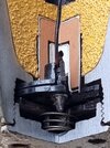
Cutaway model of a WW2 German SD-4 HL (4 kg fragmentation - HEAT) clusterbomb.
The SD-4 HL consists of a cast iron bomb body, in which a cast iron nosepiece is screwed.
The body has a male threaded plug in the base, locking up the detonator-booster assembly in the base of the body. An eAZ66 electric impact fuze is placed in the nosepiece, locked up by the fuze retainer ring.
The tail is build up of four pressed sheet metal quarter parts, connected by spotwelds and a circular strut around the lower part of the tail. The tail is connected to the body by means of four sprongs punched into corresponding recesses in the body.
Inside the body a 32 degree trunv
ated conical steel liner is placed, flanged at the base. The flange is slotted at three points, two for the electric wires, one for the locating pin. The explosive charge - 0,31 Kg (12 Oz) TnT or TNT-RDX 46-54 -, is poured into the body through the base of the body and around the cone.
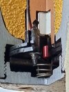
A plastic support is placed between the cone and the nosepiece. Two holes are drilled through the top of the support in which the terminal pins of the Z66 fit. From here the wiring runs down the body, placed against the wall of the body before pouring in the explosive charge. In the base of the bomb the plastic ignitor housing is placed . It consists of three stacked plastic discs, the upper has a hat shaped part that houses the Kl.Zdlg.34, below that a ring housing the wiring for the ignition squib, the lowest ring is a closure / insulation. When the male threaded basecap is placed in the base of the body, a spring is placed between cap and lower ring for insulation purposes.
Functioning of the eAZ66 (empfindliche Anschlag Zunder) Electric impact fuze:
The fuze is a plastic mould fuze (1), containing a electric spool of 54 windings copper wire (2), forming a 0,75inch dia coil. A magnitized steel cylinder (3) is placed in the centre of the coil. Above this cylinder an aluminium threaded cylinder is placed (4), housing a screw (5) over which the impeller (6) is placed. The screw has longitudal indentations (knurled) in the upper part and a small square piece is protruding from the lower side. Behind this small square piece a sping (7) is held that serves as a contact switch as soon as the screw is moved upward.
The impeller houses a spring loaded inertia bolt (8), which is housed in a of centre channel.
As soon as the bomb is released to the airstream the impeller starts to rotate the air allowed away through the holes in the fuze retaining ring. At a certain moment the rotation is sufficient to throw out the inertia bolt -compressing the spring- , enabeling the lower part of the bolt to grip into the longitudal indentations in the upper part of the screw. This will now unwind the screw, moving the impeller and screw upward and relaesing the spring-contact switch (7), closing the electric circuit. The bomb is now fully armed.
On impact the impeller, the screw and the aluminium upper cylinder are hammered inward –either straight, either angular-, hammering the magnitized cylinder down.
Moving the magnitized cylinder down induces an electric current that runs down the wire into the squib igniter (red), igniting the detonator and the Kl.Zdlg.34 and the main charge.
Length of comlete bomb : 310mm
Length of body : 212mm
Body diameter : 90 mm
The SD-4 HL bombs were used in so called AB (Abwurf Behalter) containers:
74 bombs were placed in a AB-500-1 container
40 bombs were placed in a AB-250 container
The bombs were placed nose in tail in the containers , thus increasing fuze safety.
Penetration is stated to be 130 mm steel @ 60 degrees impact angle.
Regards DJH


