pzgr40
Well-Known Member
Some General notes:The development of electrical bomb fuzes in Germany can be traced back to 1926. Under direction of Dr. H. Rhulemann it was carried out at the Rheinmetal Borsig factory. The original goal was to develop an electrical time fuze for artillery shells that could be set at the moment of firing. Somewhere down the path of development work started on Electrical bomb fuzes. This to such satisfaction that the Luftwaffe adopted the Electrical bomb fuze in 1937.
The design of most Electrical fuzes is generally the same; an aluminium outer housing, to be devided in an upper and lower housing. The upper housing has a shoulder with a locating pin, enshuring that the fuze is placed in the right direction. On top is the fuze head with the electrical plugs. The upper part normally contains the horizontal - and vertical trembler switches, resistances and the depressable pistons of the electrical plug. The lower part normally contains the condensers, the delay devices (either pyrotechnic, either mechanical) and the anti disturbance devices. The gaine is screwed in the base of the fuze. The advantages of electrical fuzes are: Easy manufacturing (low number of different components for many different functions), great flexebility, instant action, low number of duds, arming only after the pilot connects the master switch, very safe. Extensive test with electrical fields around the fuze,up to 2.000.000 volts (ligtning), showed that an electric fuze, when propperly designed, is absolutely safe.
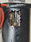
The ELAZ 55A was used in the SD (Spreng Dickwand) and the S Be (Splitter concrete) bombs. The fuze has two direct firing circuits via plunger A (the plunger on the outer edge locating pin side), and a delayed firing circuit via plunger B, with a delay of 7.5 seconds. The electric plug that is placed on the fuze has only one pin that depresses one plunger, so only Plunger A or Plunger B is electrically activated when the capacitor is charged just prior bomb discharge. The section is made over this long delay circuit (B), showing the pyrotechnic fuse (blue). Two vibrating contacts are fitted in the fuze, both positioned radially with respect to the bomb body with an angle of 90 degrees between them. What is special about this tube is the closing contact, which is placed on a rod so that the bomb explodes approximately 0.5 meters above the ground upon impact, which improves the splintering effect.style='font-size:11.0pt;font-family:"Calibri",sans-serif;color:#1F1F1F'>
Regards, DJH
The design of most Electrical fuzes is generally the same; an aluminium outer housing, to be devided in an upper and lower housing. The upper housing has a shoulder with a locating pin, enshuring that the fuze is placed in the right direction. On top is the fuze head with the electrical plugs. The upper part normally contains the horizontal - and vertical trembler switches, resistances and the depressable pistons of the electrical plug. The lower part normally contains the condensers, the delay devices (either pyrotechnic, either mechanical) and the anti disturbance devices. The gaine is screwed in the base of the fuze. The advantages of electrical fuzes are: Easy manufacturing (low number of different components for many different functions), great flexebility, instant action, low number of duds, arming only after the pilot connects the master switch, very safe. Extensive test with electrical fields around the fuze,up to 2.000.000 volts (ligtning), showed that an electric fuze, when propperly designed, is absolutely safe.
The ELAZ 55A was used in the SD (Spreng Dickwand) and the S Be (Splitter concrete) bombs. The fuze has two direct firing circuits via plunger A (the plunger on the outer edge locating pin side), and a delayed firing circuit via plunger B, with a delay of 7.5 seconds. The electric plug that is placed on the fuze has only one pin that depresses one plunger, so only Plunger A or Plunger B is electrically activated when the capacitor is charged just prior bomb discharge. The section is made over this long delay circuit (B), showing the pyrotechnic fuse (blue). Two vibrating contacts are fitted in the fuze, both positioned radially with respect to the bomb body with an angle of 90 degrees between them. What is special about this tube is the closing contact, which is placed on a rod so that the bomb explodes approximately 0.5 meters above the ground upon impact, which improves the splintering effect.style='font-size:11.0pt;font-family:"Calibri",sans-serif;color:#1F1F1F'>
Regards, DJH