pzgr40
Well-Known Member
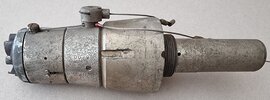
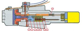
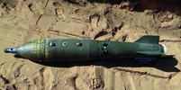
Cutaway model of a Matra 19SR nose fuze for the French 250 kg type 25 E (parachute retarded tail) or the 25D1 (with conical tail) MATRA / SAMP GP aircraft bomb. This bomb was used by the French, German and Dutch air forces until the end of the last century. The Dutch airfore used it with the NF-5 Freedom fighter only, until the NF-5 was phased out in 1991, to be replaced with the F-16. The Dutch airforce however used it with the base fuze type 20 only.
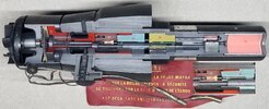
I deviated from my normal ‘no painting’ rule. As the fuze has much inner parts and the fuze is cut on two opposite sides, painting the inner parts makes it easier to recognize the inner parts per side.
Part list :
1 Fuze body
2 Filler piece
3 Nose cap
4 Guiding pin (2x)
5 Impeller
6 Roller bearing (2x)
7 Brass gearwheel with internal gear teeth (1x)
8 Ecxcentric moving gearwheel (1x)
9 Epicyclic gearweels (2x)
10 Arming bolt
11 Plunger
12 Spring ring
13 Distance discs (11x)
14 Guidance piece safety wire impeller
15 Safety wire impeller
16 Safety wire locking pin plunger
17 Pressure spring
18 Locking pin plunger
19 Arming rod
20 All ways fuze
21 Steel balls (2x)
22 Pressure spring (2x)
23 Brass release pin allways fuze
24 locking pin with spring
25 Steel ball
26 Firing pin block
27 Fixed firing pin
28 Filler piece
29 Spring housing arming rod
30 Pressure spring
31 Safety rotor
32 Duplex detonators in rotor (2x)
33 Rotation spring rotor
34 Booster housing
35 Booster in aluminium cup
36 Firing pin allways fuze
37 Pressure spring firing pin allways fuze
38 Lead (2x)
Upon bomb release the two safety wires are pulled backward.
The first safety wire (16) fixates the plunger (11) in the forward position by means of a spring (17) loaded locking pin (18). The locking pin (18) is placed in a recess in the plunger (11). The head on the safety wire has to be pulled through a thin brass ring with internal fingers that forms a resistance, preventing premature arming during installation of the bomb on the bomb rack.
The second safety wire (15) is placed in the outer circumference of the impeller (5) and prevents the impeller from rotating and arming the fuze prematurely. This wire runs through a guidance piece (14) which also houses a thin brass ring with internal fingers that forms a resistance, preventing premature arming during installation of the bomb on the bomb rack.
After bomb release both retracted wires break free from their couplings on the other side of the wire, but stay connected to the fuze body.
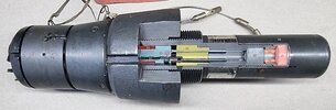
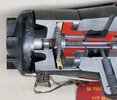
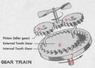
The impeller (5) starts rotating in the airstream. The small gearwheel on the end of the impeller shaft (see pictures 3 and 4) drives the two epicyclic gearwheels (9) which have an exccentric placed shaft on the base of the gear wheel. This will cause the gearheel below (8) to move eccentric circles. The eccentric gearwheel (8) drives the brass gearwheel (7) with internal tooth that starts rotating. This gearwheel is fixated to the forward flange of the arming bolt (10) by means of two screws. The arming bolt (10) now slowly starts to unscrew, moving forward. This causes the nosecap (3) together with all the connectes parts (3,4,5,6,7,8,9,10,14) to move forward. The nosecap itself however cannot rotate, as it is prevented by two guidance pins (4) that run through two longitudal slots in the nosecap, allowing it to move forward only.
As the arming bolt (10) moves forward, the aft end of the arming bolt retracts from the All ways fuze (20), partly arming the all ways fuze.
Between the fuze body (1) and the plunger (11) eleven distance discs (13) are placed in a circular array. The first and the last one are connected by a stretched leaf spring. This spring is tensioned around the stem of the plunger (11) and the other nine distance discs are placed between. If the nosecap has moved forward far enough, the distance discs are free to move outward, sweeped out by the leaf spring. Upon impact, the plunger (11) can now move inward.
Simultaniously with the moving forward of the arming bolt the spring (30) loaded arming rod (19) which is fixated in the aft position by the flange of the arming bolt (10) starts moving forward. The forward widened part of the arming rod (19) is placed in an off center hole of the all ways fuze (20), and is retracted from the hole. The all ways fuze (20) is now fully armed.
Simultaniously, the aft end of the arming rod (19) is retracted from the safety rotor (31) which is rotated 150 degrees by the rotation spring (33), rotating the two duplex detonators (32) in the safety rotor (31) between the two firing (27,36) pins and the leads (38).
The fuze is now fully armed.
If the bomb hits the ground with an angle greater that 30 degrees from the earth surface, the plunger with the connected firing pin block (26) will be pushed inward driving both firing pins (27,36) in the two duplex detonators (32). These will ignite the leads (38), which will ignite the booster (35), detonating the bomb.’
If the bomb hits the ground with an angle lower than 30 degrees from the earth surface, either makes a belly landing, the all ways fuze (20) will be activated.
Functioning of the All ways fuze (picture 02 & 05);
Before armimg of the fuze, the arming bolt (10) and the arming rod (19) fixate the inertia cilinder (20) of the all ways fuze. After arming, the inertia cilinder is only fixated by means of two spring loaded (22) steel balls (21) that are placed in a 2mm deep drilled conical hole in the Plunger (11).
To the base of the plunger the firing pin block (26) is fixated by means of four pins at 90 degrees each. The firing pin housing (26) houses a fixed firing pin (27) and a spring (37) loaded firing pin (36) activated by the all ways fuze (20).
The spring loaded firing pin of the all ways fuze is fixated in the tensioned position by a steel ball (25) that falls into a groove in the firing pin (36) which –on it’s turn- is fixated by a spring loaded locking pin (24), kept in the aft position by a brass bushing with a release pin (23). The two head sides of the pins rest against one another. Around the pin of the brass bushing (23) is a circular slot, just wider than the diameter of the spring loaded locking pin (24).
Upon impact of the bomb at an angle of less than 30 degrees, either a belly landing of the bomb inertia swings down the cilinder of the all ways fuze (20), pushing the two balls (21) back into the holes of the cilinder –riding the springs-, allowing the inertia cilinder (20) to move downward, releasing the locking pin into the circular groove of he brass bushing (23). This will allow the steel ball (25) to move inward, releasing the spring (37) loaded firing pin (36) to move into the duplex detonator. This will ignite the lead (38), which will ignite the booster (35), detonating the bomb.’
Length of the 19SR nose fuze : 288 mm
Max. diameter of the 19SR nose fuze : 87,5mm
Regards, DJH
I deviated from my normal ‘no painting’ rule. As the fuze has much inner parts and the fuze is cut on two opposite sides, painting the inner parts makes it easier to recognize the inner parts per side.
Part list :
1 Fuze body
2 Filler piece
3 Nose cap
4 Guiding pin (2x)
5 Impeller
6 Roller bearing (2x)
7 Brass gearwheel with internal gear teeth (1x)
8 Ecxcentric moving gearwheel (1x)
9 Epicyclic gearweels (2x)
10 Arming bolt
11 Plunger
12 Spring ring
13 Distance discs (11x)
14 Guidance piece safety wire impeller
15 Safety wire impeller
16 Safety wire locking pin plunger
17 Pressure spring
18 Locking pin plunger
19 Arming rod
20 All ways fuze
21 Steel balls (2x)
22 Pressure spring (2x)
23 Brass release pin allways fuze
24 locking pin with spring
25 Steel ball
26 Firing pin block
27 Fixed firing pin
28 Filler piece
29 Spring housing arming rod
30 Pressure spring
31 Safety rotor
32 Duplex detonators in rotor (2x)
33 Rotation spring rotor
34 Booster housing
35 Booster in aluminium cup
36 Firing pin allways fuze
37 Pressure spring firing pin allways fuze
38 Lead (2x)
Upon bomb release the two safety wires are pulled backward.
The first safety wire (16) fixates the plunger (11) in the forward position by means of a spring (17) loaded locking pin (18). The locking pin (18) is placed in a recess in the plunger (11). The head on the safety wire has to be pulled through a thin brass ring with internal fingers that forms a resistance, preventing premature arming during installation of the bomb on the bomb rack.
The second safety wire (15) is placed in the outer circumference of the impeller (5) and prevents the impeller from rotating and arming the fuze prematurely. This wire runs through a guidance piece (14) which also houses a thin brass ring with internal fingers that forms a resistance, preventing premature arming during installation of the bomb on the bomb rack.
After bomb release both retracted wires break free from their couplings on the other side of the wire, but stay connected to the fuze body.
The impeller (5) starts rotating in the airstream. The small gearwheel on the end of the impeller shaft (see pictures 3 and 4) drives the two epicyclic gearwheels (9) which have an exccentric placed shaft on the base of the gear wheel. This will cause the gearheel below (8) to move eccentric circles. The eccentric gearwheel (8) drives the brass gearwheel (7) with internal tooth that starts rotating. This gearwheel is fixated to the forward flange of the arming bolt (10) by means of two screws. The arming bolt (10) now slowly starts to unscrew, moving forward. This causes the nosecap (3) together with all the connectes parts (3,4,5,6,7,8,9,10,14) to move forward. The nosecap itself however cannot rotate, as it is prevented by two guidance pins (4) that run through two longitudal slots in the nosecap, allowing it to move forward only.
As the arming bolt (10) moves forward, the aft end of the arming bolt retracts from the All ways fuze (20), partly arming the all ways fuze.
Between the fuze body (1) and the plunger (11) eleven distance discs (13) are placed in a circular array. The first and the last one are connected by a stretched leaf spring. This spring is tensioned around the stem of the plunger (11) and the other nine distance discs are placed between. If the nosecap has moved forward far enough, the distance discs are free to move outward, sweeped out by the leaf spring. Upon impact, the plunger (11) can now move inward.
Simultaniously with the moving forward of the arming bolt the spring (30) loaded arming rod (19) which is fixated in the aft position by the flange of the arming bolt (10) starts moving forward. The forward widened part of the arming rod (19) is placed in an off center hole of the all ways fuze (20), and is retracted from the hole. The all ways fuze (20) is now fully armed.
Simultaniously, the aft end of the arming rod (19) is retracted from the safety rotor (31) which is rotated 150 degrees by the rotation spring (33), rotating the two duplex detonators (32) in the safety rotor (31) between the two firing (27,36) pins and the leads (38).
The fuze is now fully armed.
If the bomb hits the ground with an angle greater that 30 degrees from the earth surface, the plunger with the connected firing pin block (26) will be pushed inward driving both firing pins (27,36) in the two duplex detonators (32). These will ignite the leads (38), which will ignite the booster (35), detonating the bomb.’
If the bomb hits the ground with an angle lower than 30 degrees from the earth surface, either makes a belly landing, the all ways fuze (20) will be activated.
Functioning of the All ways fuze (picture 02 & 05);
Before armimg of the fuze, the arming bolt (10) and the arming rod (19) fixate the inertia cilinder (20) of the all ways fuze. After arming, the inertia cilinder is only fixated by means of two spring loaded (22) steel balls (21) that are placed in a 2mm deep drilled conical hole in the Plunger (11).
To the base of the plunger the firing pin block (26) is fixated by means of four pins at 90 degrees each. The firing pin housing (26) houses a fixed firing pin (27) and a spring (37) loaded firing pin (36) activated by the all ways fuze (20).
The spring loaded firing pin of the all ways fuze is fixated in the tensioned position by a steel ball (25) that falls into a groove in the firing pin (36) which –on it’s turn- is fixated by a spring loaded locking pin (24), kept in the aft position by a brass bushing with a release pin (23). The two head sides of the pins rest against one another. Around the pin of the brass bushing (23) is a circular slot, just wider than the diameter of the spring loaded locking pin (24).
Upon impact of the bomb at an angle of less than 30 degrees, either a belly landing of the bomb inertia swings down the cilinder of the all ways fuze (20), pushing the two balls (21) back into the holes of the cilinder –riding the springs-, allowing the inertia cilinder (20) to move downward, releasing the locking pin into the circular groove of he brass bushing (23). This will allow the steel ball (25) to move inward, releasing the spring (37) loaded firing pin (36) to move into the duplex detonator. This will ignite the lead (38), which will ignite the booster (35), detonating the bomb.’
Length of the 19SR nose fuze : 288 mm
Max. diameter of the 19SR nose fuze : 87,5mm
Regards, DJH
Attachments
-
 Pict 01 - Neusbuis 19SR.jpg905 KB · Views: 21
 -
 Pict 02 - 19SR nosefuze cutaway model.jpg1.4 MB · Views: 23
 -
 Pict 03 - 19SR nosefuze backside cutaway model.jpg1 MB · Views: 21
 -
 Pict 04 - 19SR nosefuze detail geartrain.jpg1.2 MB · Views: 20
 -
 Pict 05 - 19SR details all ways fuze.jpg130.4 KB · Views: 20
 -
 Pict 06 - Gear train.jpg83.4 KB · Views: 15
 -
 Pict 07 - bomb GP MATRA 250kg 25E.jpg7.1 MB · Views: 20
Last edited: